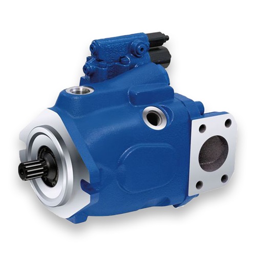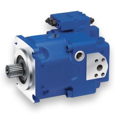
Home » Product Center » A10VO_52 series axial piston pump
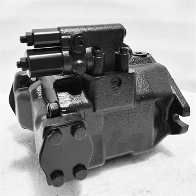
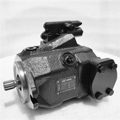
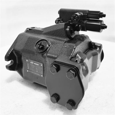
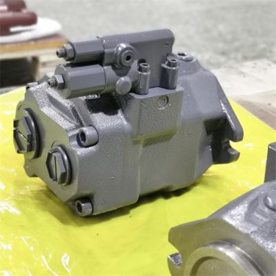
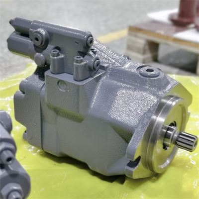
Foshan Chuangli Le Hydraulic Co., Ltd. specializes in R & D and manufacturing of hydraulic components. The products cover hydraulic pumps, hydraulic valves, hydraulic cylinders, hydraulic power units, etc., which are widely used in construction machinery, metallurgical equipment, shipbuilding, automobile production lines and other fields. Source factory direct supply, quality assurance, support non-standard customization.
Foshan Chuanglile Hydraulic Co., Ltd.
Email: creales@163.com
Address: Nanxing Industrial Zone, Guicheng, Nanhai District, Foshan City
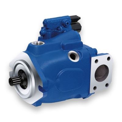
| Series | A10VO Axial Piston Variable Pump |
Specifications | 071、100、140、180 | |
Work stress | Common pressure 400bar(40Mpa), peak pressure 450bar(45Mpa) | |
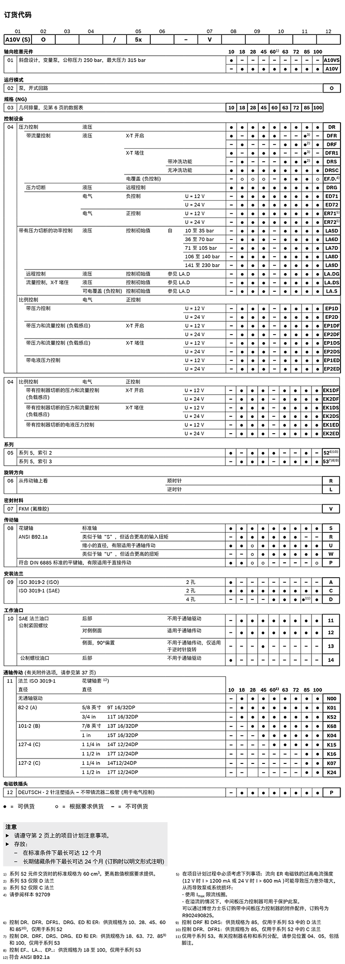
| Technical Data DG-two-point direct-acting control DR-pressure control DRG-Remote Pressure Control DRF/DRS-Pressure and Flow Control LA... -Pressure, flow and power control ED-electro-hydraulic control ER-electro-hydraulic control
| Characteristics | Axial piston variable pump of swash plate construction for hydrostatic transmission in open circuitsThe flow rate is proportional to the transmission speed and displacement.By adjusting the angle of the swash plate, the stepless change of the flow rate can be realized.Hydrostatic unloading of cradle bearingsUsed for high-pressure oil port of specification 180 or oil port connection plate of specification 22 Oil port of the measuring sensorLicensed for high speedLow noise levelIncreased functional reliabilityIdeal power-to-weight ratioUniversal through shaft drive for specification 180
|
Technical Data Sheet
Series 32
Specifications 71 to 180
Nominal pressure 280 bar
Maximum pressure 350 bar
open loop
Characteristics
Axial piston variable pump of swash plate construction for hydrostatic transmission in open circuits
The flow rate is proportional to the transmission speed and displacement.
By adjusting the angle of the swash plate, the stepless change of the flow rate can be realized.
Hydrostatic unloading of cradle bearings
Used for high-pressure oil port of specification 180 or oil port connection plate of specification 22
Oil port of the measuring sensor
Licensed for high speed
Low noise level
Increased functional reliability
Ideal power-to-weight ratio
Universal through shaft drive for specification 180
Safety Instructions
– A10VOThe pump is designed for use in an open circuit.
– Project planning, assembly and commissioning of axial plunger units must be carried out by qualified personnel.
– Read the corresponding instruction manual completely before using the axial plunger unit. If necessary, request these manuals from Bosch Rexroth.
– There is a risk of burns to the axial plunger unit, in particular the electromagnet, during and shortly after operation. Appropriate safety measures should be taken (e.g., wearing protective clothing).
– Depending on the operating conditions (operating pressure, oil temperature) of the axial plunger unit, the characteristics may change.
– Port of working line:
The oil ports and mounting threads are designed for the maximum specified pressure. Machine or system manufacturers must ensure that the safety factors of connecting components and pipelines meet the specified operating conditions (pressure, flow rate, hydraulic fluid, and temperature).
The working and functional oil ports are designed for hydraulic lines only.
– Pressure cut-off and pressure control do not provide overpressure protection. A separate relief valve is provided in the hydraulic system.
– The data and instructions contained herein must be followed.
– The product cannot be approved as a component that follows the general mechanical safety concept of ISO 13849.
– Use the following tightening torques:
· Joint:
See manufacturer's instructions for tightening torque of the joint used.
· Mounting bolt:
For mounting bolts that comply with the ISO metric thread standard of DIN 13 and the thread standard of ASME B1.1, we recommend to check the tightening torque separately according to the VDI 2230.
· Threaded hole of axial plunger unit:
The maximum allowable tightening torque, MG max, is the upper limit for threaded holes and must not be exceeded. See the table below for numerical values.
· Locking screw:
For the metal locking screw provided with the axial plunger unit, a tightening torque MV needs to be applied.
Installation Instructions
During commissioning and operation, the axial piston unit must always be filled with hydraulic oil and discharged with air. In the case of relatively long outages, the above precautions should also be observed, since the axial piston unit is emptied via the hydraulic line.
Especially in the "drive shaft up/down" installation position, it must be thoroughly filled with oil and exhaust, otherwise there will be danger of oil-free operation.
The case drain in the motor housing must be drained to the tank through the highest case drain ports (L1, L2, L3).
For combinations of multiple devices, it should be ensured that the corresponding housing pressure of each device is not exceeded. When there is a differential pressure at the drain of the equipment, the common drain line must be replaced so that the minimum allowable case pressure for all connected equipment is not exceeded in any case. If this is not possible, separate drain lines shall be laid if necessary.
In order to obtain favorable noise values, all connecting lines should be separated with elastic elements and installation above the tank should be avoided.
Under all operating conditions, the suction line and the case drain line must be connected to a position below the minimum oil level in the oil tank. The allowable oil suction height hS depends on the total pressure loss, but does not exceed its maximum value (hS max = 800mm). The minimum suction pressure at port S must also not fall below 0.8 bar absolute during operation.
Installation location
See Examples 1 to 12 below.
Other mounting locations are available upon request.
Recommended installation locations: 1 and 3.
Attention
You may find that certain installation locations have an impact on the control device. Due to the presence of gravity, component weight and shell pressure, the characteristic displacement and response time may change slightly. Installation under the fuel tank (standard) Installation under the fuel tank means that the axial plunger unit is installed outside the fuel tank, below the minimum oil level.
Installation above the tank
Mounting above the tank means that the axial plunger unit is mounted above the lowest oil level of the tank.
In order to prevent the axial plunger unit from emptying, a height difference hES min of at least 25 mm is required for installation position 6 to comply with the requirement of maximum allowable oil suction height hS max = 800mm.
The check valve in the case drain line is only permitted in isolated conditions. For certification information please contact us.
Installation in the fuel tank
In-tank installation means that the pump is installed within the minimum tank oil level.
Axial plunger units with electrical components (e. g. electronic controls, sensors) cannot be installed below the oil level of the oil tank.
Copyright©2025-2026 Foshan Chuanglile Hydraulic Co., Ltd. Copyright All Rights Reserved.